
Oculus have recently released their passthrough API to enable developers to produce augmented reality applications for the Oculus Quest headsets. Yep, you heard me right, your VR headset is now also an AR headset, (and just by updating it)! If you’re anything like us, what you probably want to know is whether it’s any good? Does your VR headset really need an AR feature?
First things first, lets get it set up so you can see for yourself. Then once its set up, lets look at sweating the AR feature into something useful!
Setup
Before you work your way through this, its important to note that this is an experimental update. This means it’s early doors still and it’s not widely adopted, therefore you must have the right settings for this to be able to work. Long story short, make sure you do ALL the things on this list!
Project Foundations
- Create a new Unity project using LTS 2019.4.29f1, I did manage to get it working in later versions however I’d recommend going with the LTS version as we know that’s a solid working version of Unity.
- File Tab/Build Settings – Change Platform to Android if not already on Android
- Download V31.2 Oculus Integration from here. Its important to note that if you download the Oculus Integration from the asset store you will get V32.0 which DOES NOT have the passthrough features.


- Install the package and upgrade if prompted, restart if prompted.
- Edit Tab/Project Settings/XR Plugin Management – Install XR Plugin Management, enable oculus for android.

- Edit Tab/Project Settings/Player
- Minimum API = API Level 23 (Android 6.0 Marshmallow)
- Scripting Backend = IL2CPP
- Colour Space = Linear
- Architecture = ARM64
- Oculus Tab/Tools/Open XR/Switch to OVR Plugin with OpenXR Backend, restart if prompted
Loading the Scene
- Assets/Oculus/SampleFramework/Usage/Passthrough/Scenes/Augmented Objects

- File Tab/Build Settings – Add all open scenes
- Under the OVR Camera Rig game object, tick Experimental options and enable passthrough features.

- Oculus Tab/Tools/Create store compatible Android Manifest.XML – This adds the experimental features to the preexisting android manifest
Windows Commands
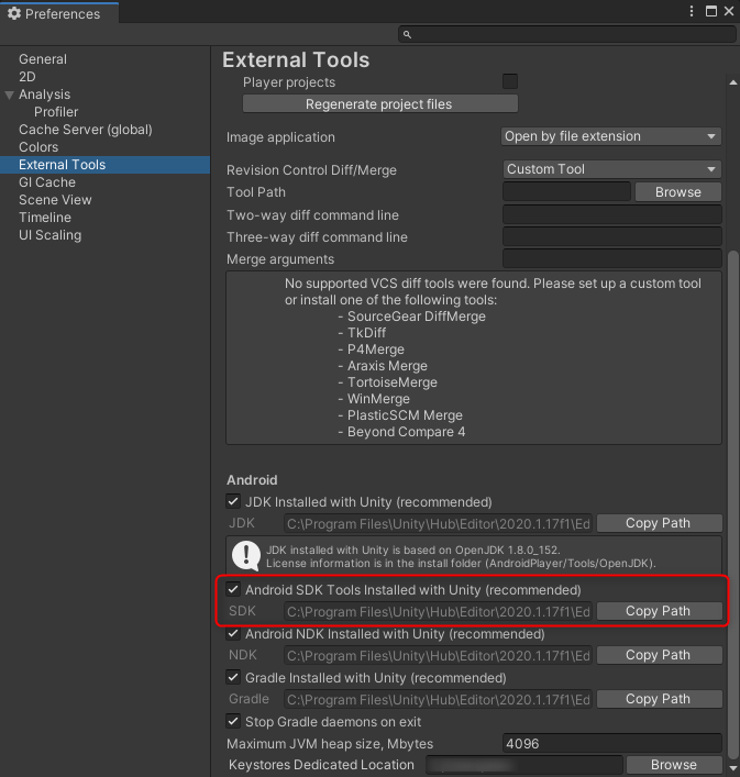
- Edit Tab/Preferences/External Tools – Copy the path of the Android SDK
- Open up windows command prompt (cmd in windows search bar)
- Type cd, then paste the path of the Android SDK we just copied. Depending on whether you’re using powershell or windows command shell you may need to wrap the pasted path in quotation marks.
- Type adb.exe If nothing runs, make sure Android Debug Bridge is set up.
- Once set up, plug in the Oculus Headset and make sure data transfer is enabled when prompted in the headset.
- Then paste the following text into the windows command shell:
adb shell setprop debug.oculus.experimentalEnabled 1
- File Tab/Build Settings/Build and Run (Make sure oculus device is selected in run device)
Hotfixes
- If you are having troubles with the Unity Build and Run function, it may also be worth trying the Build and Run function in the Oculus Tab (Oculus Tab/OVR Build/OVR Build APK and Run)
- Another recommendation is to reset all experimental features under the experimental tab within the oculus headset. This will restart the headset, once restarted, run the adb command again to set the experimentalEnabled to 1.
- I noticed that when I added the OVRInput feature into a C# script and added that to the scene, it stopped working and the scene was entirely black. Odd as the syntax is the same as scripts already in the scene, perhaps I missed something but I did manage to replicate it twice!
Making a measurement tool
Phew! That was a lot but its these kinds of hoops you have to jump through when working with experimental features. It will all be worth it I promise! So how can we turn this feature into a tool? How about a measurement tool?
You may have got some of the sample scenes to work, specifically for this next part, we’re going to adapt the “Augmented Objects” scene to make the measurement tool to enable us to measure objects within the room you’re in.
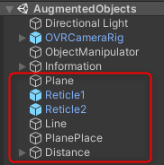
Firstly In addition to the game objects already in the scene we need to add:
- A plane to act as our ground
- Two reticles to measure between
- A line renderer to draw a line between the two reticles
- A place plane script (below)
- A canvas to present the distance calculated between two points and a script to do the work for us (also below)
Placing the plane
Below is a simple script that takes the position of the left controller, the plane and the two reticles. All it does is get the height of the controller (transform Y) and set the reticles and plane to that value on their Y axis.
using UnityEngine;

public class PlaceGround : MonoBehaviour
{
    public GameObject groundPlane;
    public GameObject controllerAnchor;
    public GameObject reticle1;
    public GameObject reticle2;

    void Update()
    {
        float controllerAnchorHeight = controllerAnchor.transform.position.y;
        groundPlane.transform.position = new Vector3(0, controllerAnchorHeight, 0);
        reticle1.transform.position = new Vector3(reticle1.transform.position.x, controllerAnchorHeight, reticle1.transform.position.z);
        reticle2.transform.position = new Vector3(reticle2.transform.position.x, controllerAnchorHeight, reticle2.transform.position.z);
    }
}
Once this is set, all we need to do is place our left controller on the ground and the plane will follow, the reticles will also snap to the plane.
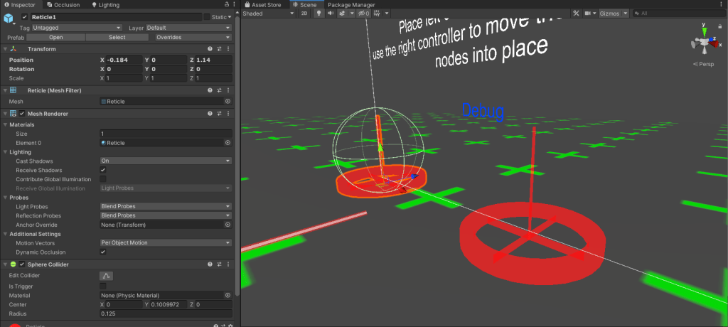
Creating the Reticles
Your reticles can be anything you like (small sphere, cube, cone), but for me I wanted something with a bit more precision, so I put something together in an external modelling software. After dropping the mesh in, I added a material and sphere collider to them. This will mean that with the code provided under ‘Object manipulator’, we can now interact with them and move them about the scene.
Draw a Line
We then needed to draw a line and calculate the distance between the two. Thanks to Gyanendu Shekhar for the code below:
using UnityEngine;

public class DrawLine : MonoBehaviour
{
    // Apply these values in the editor
    public LineRenderer LineRenderer;
    public Transform TransformOne;
    public Transform TransformTwo;

    void Update()
    {
        // set the color of the line
        LineRenderer.startColor = Color.red;
        LineRenderer.endColor = Color.red;

        // set width of the renderer
        LineRenderer.startWidth = 0.01f;
        LineRenderer.endWidth = 0.01f;

        // set the position
        LineRenderer.SetPosition(0, TransformOne.position);
        LineRenderer.SetPosition(1, TransformTwo.position);
    }
}
All this does is get the position of the two reticles and draws a line between them. You may have also spotted that it will set the colour and width too, pretty neat!
Distance Text
So by now we should have a ground plane, two reticles that can move about the scene and line drawn between them. But now we need to know how long that line is!
using System.Collections;
using System.Collections.Generic;
using UnityEngine;

public class DistanceText : MonoBehaviour
{
    public GameObject reticle1;
    public GameObject reticle2;
    public GameObject distanceText;
    public GameObject distanceTextCanvas;
    public GameObject debugText;

    private float distance;

    void Update()
    {
        distanceTextCanvas.transform.position = reticle2.transform.position + ((reticle1.transform.position - reticle2.transform.position) * 0.5f);
        distanceTextCanvas.transform.LookAt(Camera.main.transform);
        distanceText.GetComponent<TextMesh>().text = Vector3.Distance(reticle1.transform.position, reticle2.transform.position).ToString("F2") + "m";
    }
From top to bottom this is what the script does:
- Gets the position of the two reticles and calculates the midpoint between them
- Makes the text look at the camera at all times
- Converts the distance between the two reticles into a string and pushes that through to the text mesh canvas to render.
Once that’s all dropped in and linked up, you should have something like this:
Conclusion
So as you may have seen from the video, we weren’t too far off in terms of distance! I measured a few lengths of wall, firstly in the quest, then secondly with a laser measure and these were the results:
| Oculus Measured Distance | Laser Measured Distance | Difference |
| 1.01m | 1.02m | +10mm |
| 1.90m | 1.94m | +40mm |
| 3.89m | 3.73m | -160mm |
| 5.65m | 5.84m | +190mm |
Possibly as expected, the tolerance increases as the measured distance increases. It’s not quite workable in terms of building from it, but as a rough dimension, to be out by 200mm at almost 6m is very impressive! Especially considering this is a purely from a software update and a a few lines of code in Unity.
Further development can be placing the plane on the ground and it being fixed there rather than having to put the controller on the floor. Instead of moving objects in the scene, these could be spawned and chained to form a room bounding of sorts, similar to how a room-scale guardian boundary is drawn.
Let us know your thoughts? We’d love to hear how you got on with this passthrough feature!
